
Description E3D Draft Commands
| Copy Box East | New Box CopyPrev By E 1000 Wrt/* | |
| Dtangle Horizontal | Dtoffset 0 3 | |
| Delete Gap | Gap Delete @ | |
| Leader Bent | Lead Bent Atta At@ | |
| Overshoot | Overshoot@ | |
| Del Text | Delete Texp Id@ | |
| Plcl@ | Plcl@ | |
| Stra By X | New Stra Copy PrevBy X 6 | |
| Stra By Y | New Stra Copy Prev ByY 10 | |
| Lead Atta | Lead Atta At@ | |
| Lead Fa | Lleader False | |
| Remove thetext cline text | Pltxt Unset | |
| Dt Angv | Dtang Ver Dtoffset 0 3 | |
| Dt Angh | Dtang Hor Dtoffset 0 3 | |
| Pltx Thor | Ptang Hor | |
| Pltx Tver | Ptang Ver | |
| Q Pltxt | Q Pltxt | |
| Move the Dim | At@ | |
| Rotation of View | Adeg 180 | |
| Rotation of View | Adeg 270 | |
| Rotation of View | Adeg0 | |
| Rotation of View | Adeg 90 | |
| New Symb | New Symb Copy Pre At@ | |
| Rename the slab | Ddnm Id@ | |
| Slab copy | New Slab Copy Prev At@ | |
| Move by horizontal | By X 10 | |
| Move by horizontal | By Y 10 | |
| By -X10 | By X -10 | |
| By -Y10 | By Y -10 | |
| Change the scale of view | Q Xyscale .375 .375 | |
| New text copy | New Texp Copy Pre By Y 10 | |
| Ptof10 | Ptoffset 10 | |
| Ptoff5 | Ptoffset 5 | |
| Elevation dim | Pltxt ‘#Pipe(C2:)~C El.+#Posu(C2:)’ | |
| Pltxtn | Pltxt ‘#Pipe(C2:)’ |
Main Features of E3D Draft Commands
Drawing Setup
- Initiate new drawings or open existing sheets.
- Define borders, frames, and title blocks according to project standards.
View Extraction
- Pull orthographic, isometric, or perspective views from the live 3D model.
- Control projection angles, scales, and positioning with precision.
Annotation Tools
- Insert dimensions, leader notes, weld marks, and equipment tags.
- Maintain clarity and compliance with drafting standards.
Sections and Details
- Generate section cuts or detailed blow-up views for complex equipment or piping.
- Highlight critical components for construction teams.
Editing and Formatting
- Adjust line styles, fonts, and dimension settings.
- Customize the drawing appearance to meet client requirements.
Output and Updates
- Export drawings to formats like DWG, DXF, or PDF.
- Keep drawings synchronized with model changes to avoid inconsistencies.
Above mention commands are E3D draft commands, which are helpful for generating the drawings in E3d.
Using E3D Draft commands ensures drawings are produced quickly, remain consistent with the 3D model, and meet industry standards. This reduces rework, enhances accuracy, and speeds up project delivery.
FAQ
1. What exactly are E3D Draft Commands?
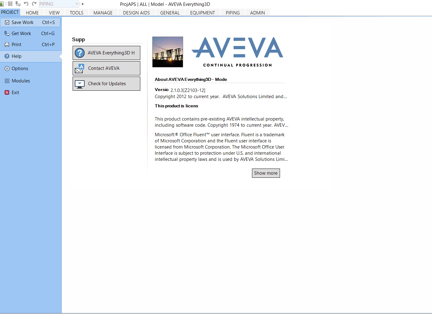
E3D Draft commands are specialized functions inside the AVEVA E3D Draft environment that allow designers to create and control 2D drawings from 3D models. They help transform complex digital models into clear, standardized engineering documents.
2. Why should engineers use E3D Draft Commands?
These commands reduce manual effort, cut down on errors, and keep drawings automatically linked with the 3D model. This ensures that every drawing reflects the most up-to-date design without extra rework.
3. What kind of drawings can be produced?
With Draft commands, users can generate a wide range of deliverables such as piping plans, equipment layouts, fabrication drawings, sectional views, and overall plant arrangements.
4. Do drawings stay connected to the 3D model?
Yes. One of the strengths of the Draft module is its associativity. Any change in the 3D model can be refreshed into the drawings, ensuring consistency between design and documentation.
5. Which commands are commonly used in Draft?
Frequent commands include tools for creating views, applying dimensions, adding text notes, producing sectional views, and inserting engineering symbols or labels.
6. How can Draft drawings be shared outside E3D?
Outputs from Draft can be exported in widely used formats like PDF, DWG, or DXF, making them easy to share with clients, vendors, or construction teams.