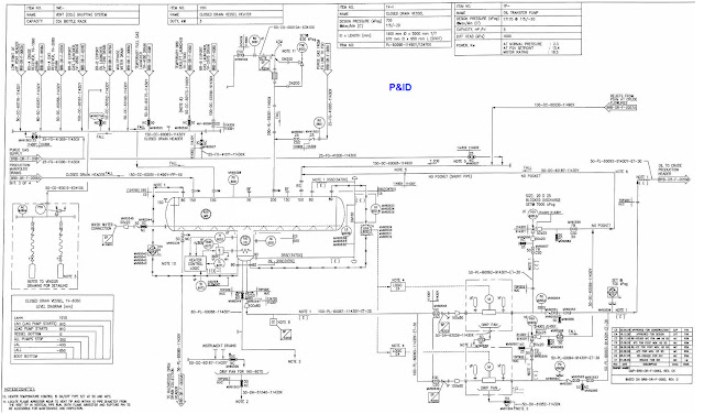
A piping and instrumentation diagram (P&ID) is a schematic diagram that shows the piping and process equipment together with the instrumentation and control devices for a process system.
P&ID is used in the process industries to design, construct, and operate plants. P& ID is a diagram in the process industry which shows the piping of the process flow together with the installed equipment and instrumentation.
A Piping and Instrumentation Diagram (P&ID) is a drawing made during the design phase that shows in depth the piping and instrumentation of a processing plant. P&ID is then used to help build and run the related plant.
Process design engineers make the P&IDs of a plant, which are then used by instrumentation and pipe engineers. During the planning phase of a plant, a P&ID is usually made from a Process Flow Diagram (PFD), which shows how the main process flows.
What are items that included on the piping and instrumentation diagram?
- Instrumentation and designations
- Mechanical equipment with names and numbers
- All valves and their identifications
- Process piping, sizes and identification
- Miscellanea – vents, drains, special fittings, sampling
lines, reducers, etc. - Permanent start-up and flush lines
- Flow directions
- Interconnections references
- Control inputs and outputs, interlocks
- Interfaces for class changes
- Computer control system input
- Identification of components and subsystems delivered by others
What documents referred for piping and instrumentation diagram P&ID
Process flow diagrams (PFDs): PFDs show the overall flow of the process, including the major components and their interactions. They are often used to create the P&ID.
Instrument datasheets: Instrument datasheets provide detailed information about the instruments that are used in the process. This information includes the type of instrument, its function, its specifications, and its location.
Piping material specifications (PMS): PMSs provide information about the materials that are used in the piping system. This information includes the type of material, its properties, and its specifications
Equipment datasheets: Equipment datasheets provide detailed information about the equipment that is used in the process. This information includes the type of equipment, its function, its specifications, and its location.
Hook-up diagrams: Hook-up diagrams show the connections between the different components of the process. They are often used to troubleshoot problems with the process.
Instrumentation logic diagrams (ILDs): ILDs show the logic that is used to control the process. They are often used to understand how the process works and to make changes to the control system.
P&ID contain the below information
- Lines: Reference tag numbers, pipe material class, line size, fluid service, insulator type and thickness, etc. On the P&ID lines, data about the process, such as the pressure, temperature, and flow rates of the lines, is sometimes also shown.
- P&IDs also show other pipe requirements, like slope, special shielding like heat tracing, minimum/maximum pipe distance requirements, and their values.
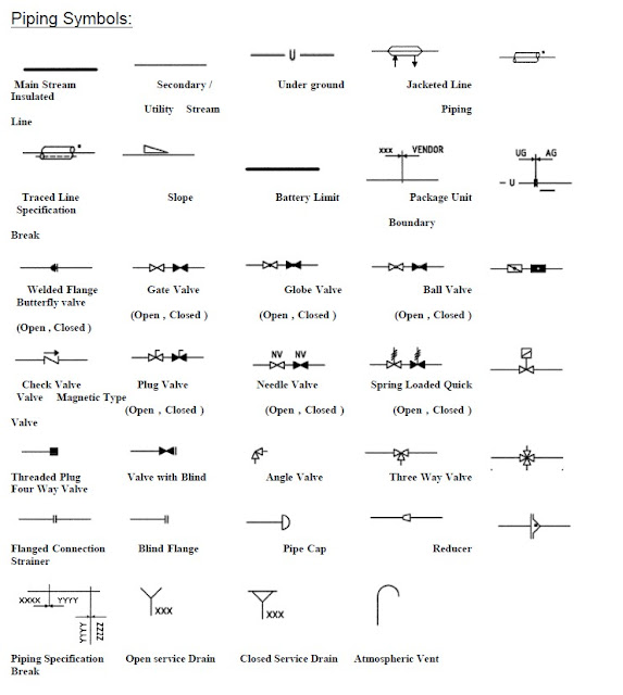
- Valve types (ball valve, gate valve, check valve, etc.), size, and how they are handled by hand. Locked shut/open, sealed shut/open, usually shut/open, and so on.
- Pipe connections, such as flanges, reducers/expanders, spectacle blinds, spacers, strainers, etc., with their sizes where needed.
- Drains and vents are generally shown with standard symbols and information about their size and type (single valve, double valve, etc.).
- Automated valves: If the size is known, the size of shutdown valves (SDV), control valves (CV), and blowdown valves (BDV) is shown. For each of these valves, the fail position (fail open, fail close, or fail in position) is also shown. Actuator type and link are shown. On every motorised valve, there is a reference instrument tag number.
- Safety Valves: The setpoints and types of a pressure relief valve (PRV) or a temperature relief valve (TRV) are shown by different marks on the instrument tag.
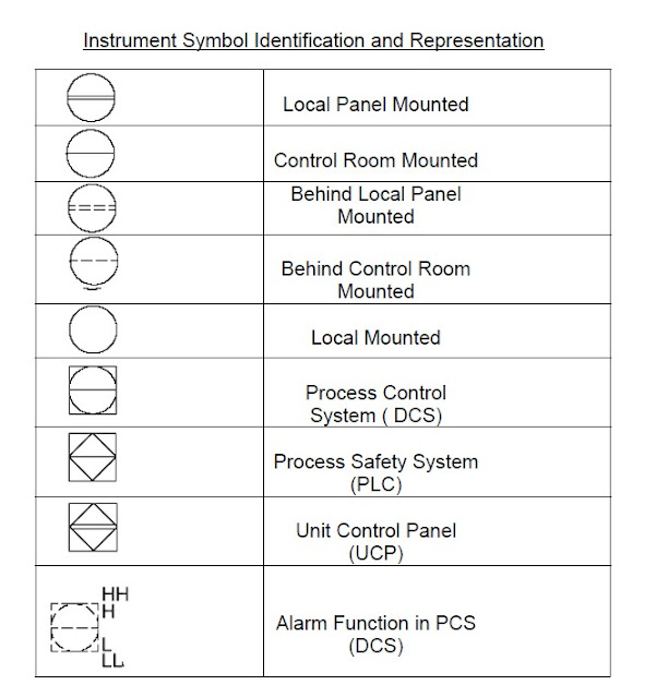
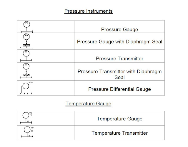
- Instruments: The P&ID must include detailed information about gauges, sensors, local indicators, DCS indicators, interlocks, and other functions. Different types of instrument outputs (hardwired signal, soft signal, pneumatic or hydraulic signal, etc.) must show how these parts connect to each other.
- Notes are made wherever they are needed to help people who use the P&ID understand it better. “Hold” is sometimes used to show that there isn’t enough information to make a decision.
- Interconnections : Lines and instrument data from two different P&ID sheets are shown to be connected. Sometimes, a unique tag number is also given to each of these connections. To make it easy to see how two P&IDs are connected to each other. The same tag number is given to a link that is used to connect a line or signal on two different drawings.
- piping and instrumentation diagram are an important part of process safety management. They can be used to identify potential hazards and to develop control measures to mitigate those hazards.
Terminolpogy associated with piping and instrumentation diagram P&ID
P&ID symbols are used to represent different types of mechanical equipment, piping, and instrumentation on P&IDs. There is a standard set of P&ID symbols that is used by engineers around the world. This standard is maintained by the International Society of Automation (ISA).
Control system for a plant is shown on the P&ID by symbols that represent sensors, valves, and controllers. Sensors measure the process variables, such as pressure, temperature, and flow rate. Valves control the flow of materials through the plant. Controllers receive signals from the sensors and use them to adjust the valves to maintain the process variables within desired limits.
Process flow diagram (PFD) is a simplified version of the P&ID that shows the major components of the process and the flow of materials through the plant. PFDs are used to get an overview of the process and to identify potential hazards.
Piping components on a P&ID are represented by symbols that show their size, type, and function. For example, a pipe symbol will show the diameter of the pipe, the type of material the pipe is made of, and whether the pipe is a straight run or a bend and other piping components line reducers flat side up or down to meet the process requirement of the mechanical equipment / pumps. There is straight length requirement for some process mechanical equipment, that is mentioned on the p&id notes. Straight length requirement mainly on the inlet nozzle of the process or mechanical equipment.
Pressure temperature are important process variables that are shown on P&IDs. The pressure temperature of the process fluids are used to control the process and to ensure the safety of the plant.
P&IDs are an essential tool for engineers who design, construct, and operate plants in the process industries. They provide a clear and concise way to represent the physical layout of a plant, the flow of materials through the plant, and the control system for the plant. P&IDs are also an important part of process safety management (PSM). They can be used to identify potential hazards and to develop control measures to mitigate those hazards.
What is the purpose of piping and instrumentation diagram p&id
The purpose of a piping and instrumentation diagram is to provide a clear and concise way to represent the physical layout of a plant, the flow of materials through the plant, and the control system for the plant. P&IDs are also used to identify potential hazards and to develop control measures to mitigate those hazards.
- To provide a visual representation of the plant layout. P&IDs show the physical location of equipment, piping, and instrumentation in the plant. This can be helpful for understanding how the plant works and for troubleshooting problems.
- To show the flow of materials through the plant. P&IDs show the path that materials take through the plant. This can be helpful for understanding how the plant is operated and for identifying potential hazards.
- To show the control system for the plant. P&IDs show the sensors, valves, and controllers that are used to control the plant. This can be helpful for understanding how the plant is controlled and for identifying potential hazards.
- To identify potential hazards. P&IDs can be used to identify potential hazards in the plant. This is because they show the physical layout of the plant, the flow of materials through the plant, and the control system for the plant.
- To develop control measures to mitigate hazards. Once potential hazards have been identified, P&IDs can be used to develop control measures to mitigate those hazards. This can involve adding new instrumentation, valves, or controllers to the plant.
- To document the plant for future reference. P&IDs are an important part of the plant documentation for a process plant. They can be used to refer to the plant design for future reference, such as when the plant is being modified or when there is a problem with the plant.
- To communicate the plant design to engineers, operators, and maintenance personnel. P&IDs can be used to communicate the plant design to engineers, operators, and maintenance personnel. This can help to ensure that everyone involved in the plant understands how the plant works and how to operate and maintain the plant safely.
Piping and instrumentation diagram are an essential tool for engineers who design, construct, and operate plants in the process industries. They are a valuable resource for understanding the plant, troubleshooting problems, and ensuring the safety of the plant.
Benefits of using piping and instrumentation diagram P&ID
- They provide a clear and concise way to represent the physical layout of a plant, the flow of materials through the plant, and the control system for the plant. This can be helpful for understanding how the plant works and for troubleshooting problems.
- They can be used to identify potential hazards and to develop control measures to mitigate those hazards. This can help to ensure the safety of the plant.
- They are an important part of the plant documentation for a process plant. This can help to ensure that the plant is properly maintained and operated.
- They are used by engineers, operators, and maintenance personnel to understand the plant and to troubleshoot problems. This can help to ensure that the plant is operated safely and efficiently.
- They are also used by regulatory agencies to review the safety of process plants. This can help to ensure that the plant complies with all applicable regulations.
Why piping used P&ID
Piping and instrumentation Diagram (P&ID) is the main basis for designing of the piping of any plants like offshore wellheads platforms, refineries, chemical plants, power plants, process plant. P&ID contains the process parameters of system like size of line, service of the line, instruments fitting like PG, TE, PDIA CC and other information related to that service and Mechanical equipment’s.
Piping and instrumentation Diagram (P&ID) is the first documents on the basis of piping department start working on to develop the plant layout. On the basis of p&id symbols, Material engineer calculate the valve, tentative piping component, Special fitting, sampling lines, and piping material take off.
The Process Department holds the authority to tweak process parameters on the P&IDs whenever needed. This flexibility allows them to address any concerns that may arise from other disciplines involved in the project. By doing so, they maintain a harmonious collaboration, ensuring a smooth workflow throughout the entire engineering process.


2 thoughts on “What is piping and instrumentation diagram (P&ID)”